The crankshaft is drilled from the main bearings to the connecting rod bearings.
A small groove is located in the connecting rod at the mating face where the cap contacts the connecting rod.
This groove is used as an oil squirt hole for cylinder wall lubrication. Oil from the connecting rod squirt hole 7 lubricates the opposite cylinder wall. For example, the No. 1 connecting rod oils No. 5 cylinder, etc; As the -crankshaft turns, the hole in the connecting rod bearing aligns with the hole in the journal causing a direct squirt of oil onto the cylinder wall (Fig. 9).
Oil passages are drilled from the main oil gallery to each valve lifter oil gallery. Oil from here feeds the valve lifter assemblies. A reservoir at each valve lifter bore boss traps oil so that oil is available for valve lifter lubrication as soon as the engine starts.
When the hydraulic lifter is on the base circle of the camshaft lobe (valve closed), the oil hole in the hydraulic lifter and plunger is indexed with the lifter oil gallery and oil flows into the plunger. The pressure differential above and below the check valve (disc or ball check) forces the check valve open and oil fills the compression chamber below the plunger. Oil is also metered through the metering valve (disc) through the oil passages in the push rod cup and then flows up the hollow push rod.
In this position, the drilled hole in the ball end of the push rod Is Indexed with a drilled hole in the rocker arm and the oil lubricates the upper valve train bearing areas (Fig. 9). Excess oil is returned to the oil pan through drain back holes located at each end of the cylinder head and block (Fig. 9).
|
Positive crankcase ventilation system
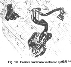
The air flow in the positive crankcase ventilation system is shown in Fig. 10.
Ventilating air enters the engine through the oil filler cap located on the front of the left valve rocker arm cover. The filler cap contains a filtering element which filters the incoming air.
From the oil filter cap, the air flows into the front section of the valve rocker arm shaft chamber. The ventilating air moves down past the push rods into the front of the lower crankcase and into the timing chain chamber.
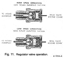
The rotating action of the crankshaft causes the air to flow towards the rear of the crankcase and up into the rear section of the right valve rocker arm cover. The air then enters a spring-loaded regulator valve that regulates the amount of air to meet changing operating conditions. The air is then directed to the intake manifold through the crankcase vent hose.
During idle, intake manifold vacuum is high. The high vacuum overcomes the tension, of the spring pressure and seats the valve (Fig. 11). With the valve in this position, all the ventilating air passes through a cali-brated orifice in the valve. With the valve seated, there is minimum ventilation. As engine speed increases and manifold vacuum decreases, the spring forces the valve off its seat and to the full open position (Fig. 11). This increases the flow of ventilating air.
|
 **
**

