Dismantling
- Remove the oil inlet tube from the oil pump and remove the gasket.
- Remove the cover retaining screws, then remove the cover. Remove the inner rotor and shaft assembly, then remove the outer race.
- Insert a self-threading sheet metal screw of the proper diameter into the oil pressure relief valve chamber cap and pull the cap out of the chamber. Remove the spring and plunger.
Cleaning
Wash all parts in a solvent and dry them thoroughly with compressed air. Use a brush to clean the inside of the pump housing and the pressure relief valve chamber. Be sure all dirt and metal particles are removed.
Inspection
Check the inside of the pump housing and the outer race and rotor for damage or excessive wear.
Check the mating surface of the pump cover for wear. If the cover mating surface is worn, scored, or grooved, replace the cover.
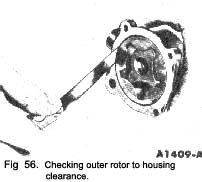
Measure the outer race to housing clearance (Fig. 56) which should be ~OO6 ins.—012 ins.
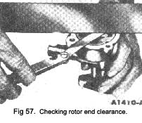
With the rotor assembly installed in the housing, place a straight edge over the rotor assembly and the housing. Measure the clearance between the straight edge and the -rotor and outer race (Fig. 57) which should be - 001 ins.—004 ins.
The outer race, shaft and rotor are replaceable only as an assembly.
Check the drive shaft to housing bearing clearance by _ measuring the OD of the shaft and the ID of the housing bearing.
|
Inspect the relief valve spring for a collapsed or worn condition.
Check the relief valve spring tension. This should be 1115 lbs. to 11’75 lbs. when the spring length is com-pressed to 17 ins. If the spring tension is not within these figures and/or the spring is defective, replace the spring.
Check the relief valve piston for scores and free operation in the bore.
Assembly
The oil pump assembly is shown In Fig. 55.
- Oil all parts thoroughly.
- Install the oil pressure relief valve plunger, spring and a new cap.
- Install the outer race, and the inner rotor and shaft assembly. The inner rotor and shaft, and the outer race are serviced as an assembly. One part should not be replaced without replacing the other. Install the cover and tighten the cover retaining screws.
- Position a new gasket and the oil inlet tube on the oil pump and install the retaining bolts.
CYLINDER FRONT COVER AND TIMING
CHAIN
Removal
- Drain the cooling system and the crankcase. Dis-connect the battery ground cable.
- Disconnect the radiator upper hose at the coolant outlet housing, and the radiator lower hose at the water pump.
- Disconnect the heater hose at the water pump. Slide the water pump bypass hose clamp toward the water pump.

|
 **
**

