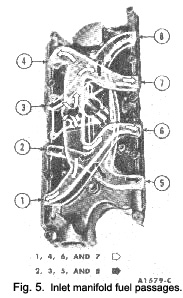
(Fig. 5). The right barrel of the carburettor feeds Nos. 1, 4, 6 and 7 cylinders and the left barrel feeds
Nos. 2, 3, 5 and 8 cylinders.
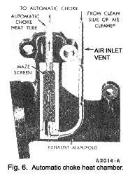
Filtered air is drawn from the air cleaner, through an air inlet tube, into the heat chamber in the right exhaust manifold. Here the air is heated and then directed to the automatic choke through the air outlet choke tube (Fig. 6).
|

Cylinder heads -
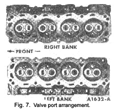
The cylinder’ head assemblies ‘contain" the valves and the valve rocker arm assemblies. The valve guides and push rod guides are machined in the head with a cast combustion chamber. The valve arrangement from front to rear on the left bank is E-I-E-l-E-l-E-l and on the right bank I-E-I-E-l-E-I-E. (Fig. .7).
Cylinder block
The cylinders are numbered from front to rear, on the right bank 1, 2, 3 and 4 and on the left bank 5, 6, 7 and 8. The firing order is 1-542-6-3-7-8.
The oil pump, mounted inside the oil pan at the left front, is driven by the distributor through an intermediate drive shaft.
The crankshaft is supported by five main bearings. Crankshaft end thrust is controlled by the flanges of the No. 3 main bearing.
The pistons have two compression rings and one oil control ring. The top compression ring is chrome-plated and the lower compression ring is phosphate-coated. The oil control ring assembly consists of a serrated spring and two chrome-plated steel rails.
Valve train
The push rods are tubular steel with ball ends. The push rods supply oil from a metering valve (disc) in the hydraulic valve lifters through drilled holes in the bail ends for independent lubrication of each rocker arm.
The rocker arms have a drilled hole in the push rod end for lubrication. They are individually mounted on a stud that is pressed into the cylinder head. A fulcrum seat controls the rocker motion and a nut secures the rocker arm on the stud.
The camshaft is supported by five stepped diameter
|
 **
**


