The piston pin is an interference fit in the connecting rod. Oversize piston pins are not recommended. Refer to the Data Section for the piston pin and con-necting rod pin bore dimensions.
Assembly
The piston, connecting rod and related parts are shown in Fig. 75. Check the fit of a new piston in the cylinder bore before assembling the piston and piston pin to the connecting rod.
The piston pin bore of a connecting rod and the diameter of the piston pin must be within specifications.
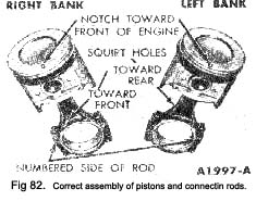
1. Apply a light coat of engine oil to all parts. Assemble the piston to the connecting rod with the oil squirt hole in the connecting rod and the indentation notch in the piston positioned as shown in Fig. 62.
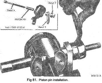
2. Start the piston pin in the piston and connecting rod. Draw the piston pin through the piston and connecting rod until the end of the pin seats in Detail 2 (Fig. 81).
3. Follow the instructions contained on the piston ring package and install the piston rings.
4. Check the ring side clearance of the compression rings with a feeler gauge inserted between the ring and its lower land. The gauge should slide freely
|
around the entire ring circumference without binding. Any wear that occurs will form a step at the Inner portion of the lower land. If the lower lands have high steps, the piston should be replaced.
5. Be sure the bearing inserts and the bearing bore in the connecting rod and cap are clean. Foreign material under the inserts may distort the bearing and cause a failure. Install the bearing inserts in the connecting rod and cap with the tangs fitting in the slots provided.
|
 **
**

