bearings pressed into the block with a dowel for position-ing the camshaft sprocket. It is driven by a sprocket and timing chain in mesh with a sprocket on the crankshaft.
Camshaft end play is controlled by a thrust plate attached to the cylinder block.
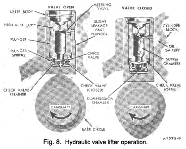
Hydraulic valve lifters are used which provide zero valve
lash. The operation and parts identification of the hydraulic valve lifters are shown In Fig. 8.
When the valve is closed, the lifter assembly is on the base circle of the camshaft lobe and the valve push rod is in its lowest position. With the lifter assembly in this position, the plunger spring expands, forcing the plunger upward. This action is transmitted to the valve rocker arm via the valve push rod until there is solid contact between the valve and the valve end of the valve rocker arm (zero valve lash). In this position, the oil hole in the lifter and plunger is indexed with the lifter oil gallery in the cylinder block.
As the lifter plunger moves upward, the volume of the compression chamber is increased, resulting in reduced
oil pressure in the compression chamber. Therefore, to equalize the resulting pressure differential between the
supply chamber and the compression chamber, the disc check valve moves off its seat and permits oil to flow from the supply chamber to the compression chamber. When the
|
compression chamber becomes filled with oil, the pressures in the two chambers are equalized. The oil flow ceases and the disc valve spring seats the disc valve and closes the disc valve port.
As the camshaft rotates, the lifter assembly is raised by the camshaft lobe. This increases the push rod force against the lifter plunger and hydraulic pressure immediately builds up in the compression chamber until it acts as a solid member of the valve operating mechanism. The lifter then becomes a hydraulic ram which forces the valve in the cylinder head to open. During this period, a slight leakage of oil past the plunger occurs (calibrated leak down rate).
As the high point of the camshaft lobe rotates and passes by the foot of the valve lifter, the valve in the cylinder head seats and the valve lifter assembly is forced down-ward. Reduced force on the lifter plunger at this time relieves the pressure on the lifter plunger and It Is free to be moved upward by the plunger spring. This action allows oil to flow once again through the Indexed oil holes in the lifter body and plunger.
The operating cycle is completed for each revolution of the camshaft. Zero clearance (lash) In the valve train mechanism is maintained at all times by the hydraulic force and expansion of the plunger spring between the lifter body and plunger.
|
 **
**
