|
Instruments – to remove and refit
Always disconnect the battery positive lead before carrying out any work behind the instrument panel to avoid the risk of short circuits.
Each Instrument is retained by a stirrup and knurled nuts, which are accessible from behind the panel. Disconnect wires, drive cable or pipe, remove bulb-holder(s) and withdraw Instrument forwards.
Refer to wiring diagram when refitting.
Horn ring, and direction indicator switch
Refer to Section J of this publication.
Electric Impulse tachometer
This Instrument is an advanced engine speed Indicator which measures revolutions per minute by “counting” electrical Impulses called for by the ignition coil.
The tachometer has no mechanical take-off and operates in the following manner
The tachometer “counts” low-tension current impulses demanded by the ignition coil by means of a transistorised printed circuit unit contained within the Instrument head. This in turn influences a D.C. voltmeter movement to which a pointer is attached, so that when the engine is running this moves round the instrument dial which is calibrated from 0-6,000 r.p.m. The accuracy of this instrument is not affected by variations in ignition timing, or gap settings of either the distributor or the plugs.
No servicing Is required of the tachometer, therefore, where the instrument becomes faulty, a new Instrument must be fitted as the unit can only be repaired by the manufacturers or their appointed agents.
Should the instrument cease to function, a check is to be made of the electrical connections to see if they are in order. If the connections prove to be correct, then the tachometer must be removed and replaced by a new unit.
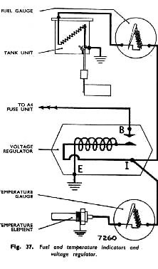
Fuel and temperature indicators
(Refer to Fig. 37).
The bimetal resistance equipment for fuel contents and temperature indication consists, in each case, of an
|
indicator head and transmitter unit connected to a common voltage regulator. In both applications the indicator head operates on a thermal principle, using a bimetal strip surrounded by a heater winding and the transmitter unit is of a resistance type.
The system by which the equipment functions is voltage sensitive and the voltage regulator which serves both indicators is necessary to ensure a constant supply of a predetermined voltage to the equipment. The regulator is situated behind the instrument panel.
The mean voltage between terminal “ I” and earth should be 10 volts. (See wiring diagram). Renew if faulty.

|
 **
**
