Front Hub Adjustment
It is essential that the end float of the front hub bearings is correct. To obtain the proper condition the following procedure must be observed—THIS IS IMPORTANT.
1. Jack up the front of the car until the road wheels are clear of the ground and remove the nave plate and the hub dust cap.
2. Extract the spilt pin locking the hub retaining nut and apply a suitable torque wrench. Tighten the hub nut until a torque reading of 15-20 lb. ft. 2.07-2.76 kg.m.) is obtained, spinning the road wheel simultaneously.
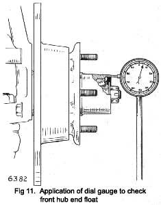
3. Release the nut to one and a half flats, spin the road wheel and check the end float by using a dial gauge.
4. If the endfloat is not within the figures quoted in the “General Data Section”, the nut must be further adjusted and the endfloat again checked with the dial gauge.
5. When the correct adjustment has been obtained, lock the castellated nut with a new split pin.
FRONT SHOCK ABSORBER
To remove and refit
1. Apply the handbrake, jack up the front of the car, remove the road wheel and support the bottom wish-bone link to bring It up to the horizontal position.
2. Detach the shock absorber at the top end by removing the two nuts, washers and rubber bush from above the spring turret.
3. Withdraw the shock absorber through the bottom link by removing two nuts and washers from the bottom mounting.
|
Editor's Note: This illustration looks NOTHING like your actual Tiger brake disc, hub and wheel mount.
4. Remove the rubber bush and washers from the top of shock absorber.
5. Remove the bottom mounting from the eye of the shock absorber by withdrawing the nut and bolt; remove the two rubber bushes by ejecting the distance piece.
6. Refitting is the reverse of the removal sequence but particular attention must be given to the following:
(I) The rubber bushes are fitted to the shock absorber eye, long tapered end first, and the mounting bracket set at an angle.
(ii) The shock absorber is fed through the bottom link in its fully extended position and so the mounting bracket is inclined downward and out-ward.
(iii) The first top nut is tightened until it bottoms and the second nut, locks the first.
|
 **
**