GENERAL DESCRIPTION-—See Figs. 1 & 2.
The pump comprises three main assemblies the main body casting (17), the diaphragm, armature, and magnet assembly (6), and the contact breaker assembly (29).
Main body
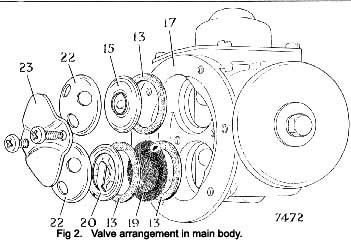
The main fuel inlet (18) is in communication with an inlet air bottle (34), and connection to the main pumping chamber (21) is provided by the inlet valve assembly (20). This comprises a Melinex valve disc permanently assem-bled within a pressed-steel cage, which is held in place by a valve cover (22). The outlet from the pumping chamber is provided with an identical valve assembly reversed in direction.
A clamp plate (23), secured by self-tapping screws (see lower diagram), holds both inlet and outlet valve assem-blies in position; the valves may be removed by re-leasing the clamp plate screws. A filter (19) is provided as shown on the entry side of the inlet valve assembly. A spring (10) loads the flexible plastic diaphragm (11), contained by the vented cover (9), is fitted across the extremity of the delivery chamber (16) sealed by the rubber ring (12). This diaphragm helps to damp out the pump pulsations.
Diaphragm, armature, and magnet assembly
The assembly comprises an Iron coil housing (6), an iron core (39), an iron armature (32), which is provided with a central spindle (38) permanently united with the dia-phragm (36), and a magnet coil (24). Eleven spherically edged rollers (33) are fitted between the coil housing and the armature; these centralize the armature within the coil housing and allow freedom of movement in a longitudinal direction.
|
Contact breaker assembly
This consists of a bakelite pedestal moulding (2) which carries two rockers (3) and (27), both hinged to the moulding at one end by the rocker spindle (26) and interconnected at their top ends by two small springs (4) arranged to give a throw-over action. The inner rocker (27) carries a trunnion (25) Into which the armature spindle (38) is screwed. The outer rocker (3) is fitted with two tungsten points which contact another two tungsten points carried by the spring blade (1). One end of the coil (24) is connected electrically to the spring blade (1) and the other end is connected to the terminal (40). A short length of flexible wire (28) con-nects the outer rocker to one of the screws securing the pedestal moulding to the coil housing, thus providing an earth return to the body of the pump; this must then be thoroughly earthed to the body or chassis of the vehicle via the earthing screw (8), as previously mentioned. The small condenser (41) is connected across the contact points to minimise sparking when the contacts break. A non-return valve (30) is fitted to the end cover moulding (42) to aid the circulation of air through the contact breaker chamber.
PUMP OPERATION—See Figs. 1 & 2.
When the pump is at rest the outer rocker (3) lies in the position illustrated and the tungsten points (29) make contact. Current passes from the Lucar connector (40) through the coil, back to the spring blade (1), through the points, and so to earth, thus energizing the coil and attracting the armature (32). The armature, together with the diaphragm assembly, moves towards the coil, against pressure from the spring (7), drawing fuel through
|
 **
**
