DESCRIPTION
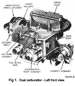
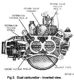
The carburettor (Figs. I and 2) has two main assemblies, the air horn and the main body.
The air horn assembly, which serves as the main body cover, contains the choke plate and the vents for the fuel bowl.
The throttle plates, the accelerating pump assembly, the power valve assembly, and the fuel bowl are in the main body. The automatic choke housing is attached to the main body.
The two barrels each contain a main and booster venturi, main fuel discharge, accelerating pump discharge, idle fuel discharge and a throttle plate.
All data such as choke tube size, jet settings, and adjustable dimensions are given in the Data Section under Fuel System.
OPERATION
Fuel Inlet System
The amount of fuel entering the fuel bowl (Fig. 3) is regulated by the distance the fuel inlet needle is raised off its seat and by fuel pump pressure. Movement of the fuel inlet needle in relation to the seat is controlled by the float and lever assembly which rises and falls with the fuel level. When the fuel in the fuel bowl reaches a pre-
|
set level, the float lowers the fuel inlet needle to a position where it restricts the flow of fuel, admitting only enough fuel to replace that being used.
An integral retracting clip is attached to the fuel Inlet needle assembly. The clip hooks over the tab of the float assembly. This clip assures reaction of the fuel Inlet needle to any downward movement of the float.
A wire-type retainer prevents movement of the float shaft within the guides on each side of the fuel bowl. The retainer fits into a groove on the outside of the fuel inlet needle seat. The ends of the retainer are hooked over grooves on opposite ends of the float shaft.
A torsion (fuel pulsation damper) spring is located on the float shaft, between the inboard end of the float retainer, and the float shaft guide in the fuel bowl. The short end of the spring rests under the float lever, and the long end of the spring rests against the inner face of the fuel bowl. The torsion spring tension resists and absorbs fuel pump pressure pulsations, and movement of fuel in the bowl due to driving conditions. This assures proper regulation of the fuel inlet needle which rises and falls with the fuel level.
The fuel bowl is internally vented into the air cleaner. It is also externally vented to the atmosphere.
|
 **
**