cam permits a faster engine idle speed for smoother running when the engine is cold during choke operation. As the choke plate is moved through its range of travel from the closed to the open position, the fast idle cam pick-up lever rotates the fast idle cam. Each position on the fast idle cam permits a slower idle r.p.m. as engine temperature rises and choking is reduced.
1. Manually rotate the fast idle cam until the fast Idle adjusting screw rests adjacent to the shoulder of the highest step (align screw with the arrow mark on the cam (Fig. 14).
2. Start the engine, and turn the fast idle adjusting screw inward or outward as required to obtain the specified fast idle r.p.m. given in the Data Section under Fuel System.
3. Remove the tachometer if the idle fuel mixture does not require adjustment. If the Idle fuel mixture requires adjustment, leave the tachometer Installed so that the idle speed can be checked after the idle fuel mixture has been adjusted.
Anti-stall dashpot adjustment—(lf fitted)
The anti-stall dashpot adjustment is made with the
carburettor air cleaner assembly removed from the -carburettor.
1. With the engine idle speed and mixture properly
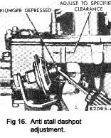
adjusted, and the engine at normal operating tem- perature, loosen the anti-stall dashpot lock nut
(Fig. 16).
2. Hold the throttle in the closed position and depress the plunger with a screwdriver blade. Check the
|
clearance between the throttle lever and the plunger tip. Turn the anti-stall dashpot in its bracket in a direction to provide a clearance of 1/16” – 3/32” between the tip of the plunger and the throttle lever. Tighten the locknut to secure the adjustment.
3. Install the air cleaner assembly.
Accelerating pump stroke adjustment
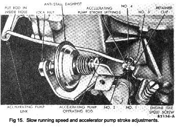
The accelerating pump stroke adjustment is made with the carburettor air cleaner removed from the carburettor. The over-travel lever on the throttle spindle has four holes and the accelerating pump link has two holes (Fig. 15) to control the accelerating pump stroke for various ambient temperatures and operating con-ditions of the engine.
The correct position for the pump link operating rod for all climatic conditions is In the Inboard hole of the link (hole closest to the pump plunger). Refer to “Carburettor” under Fuel System In the Data Section, and insert the operating rod in the proper hole of the over-travel lever to suit the climatic conditions in which the car is to be operated.
To release the operating rod from the over-travel lever, retaining clip, press the ends of the clip together; then, at the same time, press the rod away from the clip until it is disengaged. Remove the clip. To install the operating rod in the over-travel lever, install the clip on the over-travel lever. Press the ends of the clip together then at the same time, insert the rod through the clip and over-travel lever. Release the ends of the clip.
|
 **
**

