|
|
|
|
|
|
|
|
|
|
|
|
|
|
|
|
|
|
|
|
|
|
|
|
 |
|
|
|
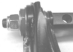
Figure 9. This is a closeup of the completed upper A-Arm showing the position of the grease fitting. Also visable in this shot is the skip weld connecting the bushing shell to the A-Arm stamping. |
|
|
|
|
|
|
|
|
|
|
|
|
 |
|
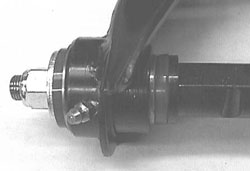
Figure 11. A closeup of the Lower A-Arm with fitting and welds. |
|
|
|
|
|
|
|
|
|
|
 |
|
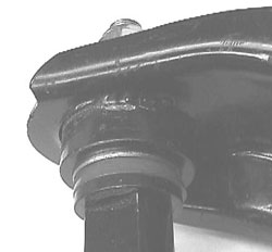
Figure 10. A closeup of the skip weld on the lower bushing shell. This is an important safety modification. Stock spin wells have been known to fail. |
|
|
|
|
|
|
|
|
 |
|
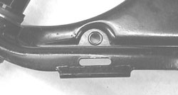
Figure 12. A shot of the reinforcement applied to the sway bar attachment point. This is a 1/4” diameter rod that is welded to bridge the slot to prevent the mounting clip from shearing the edges of the slot. Used properly, this modification will hold a 1” diameter sway bar. |
|
|
|
|
|
|
|
 |
|
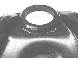
Figure 13. This is a closeup of the skip welds on the ball joint mounting ring and the Upper A-Arm. Installation of a 0.015” larger ball joint is likely to fail the OEM spin weld. This simple skip weld modification maintains this integrity and enhances safety. |
|
|
|
|
|
|
|
 |
|
|
|
|
|
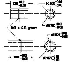
Figure 14. This is a sketch of the modified inner pivot tubes of the urethane bushings. They can be produced in a 300 series stainless steel to eliminate the chances for rust to form and cause squeeks. These may be available from Rick in the future but he won’t have them in the near term. |
|
|
 **
**


