If you end up with a “loose fit”, apply Locktite to the cleaned bushing shell before its pressed into place. This the appropriate cure to obtain proper bushing/shell adhesion with loose bushings. Your installation tooling must apply the press force to the rolled lip of the bushing shell. If you simply press on the end of the bushing, damage to the bushing is very likely to occur.
|
|
|
|
|
|
|
|
|
 |
|
|
|
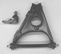
Figure 7. Here is the completed Lower A-Arm and the new lower ball joint. These new ball joints are metal to metal with no nylon inserts that could fail and allow the joint to come apart. This was the design used by the factory OEM supplier back in the 60’s. |
|
I make it a practice to install the rear bushings first. The upper A-Arms are symmetrical and interchangeable but the lowers are not. The lower fulcrum pins are machined with an offset to cause the A-Arms to be mounted toward the rear. The spacing from the front of the fulcrum pins, where they change from “double D” to round to the mounting bolt reliefs is approximately 0.9". This distance at the rear is 1.125". If you reverse this pin, you will increase the offset of the lower A-Arm forward over 0.200" increasing your static caster. This may or may not be a desired or intended consequence but at least make sure the pins on both sides are the same or your wheel alignment will be much more difficult. After you have installed the first bushing, you need to install the beveled washers on the fulcrum pin and install it into the bushing/A-Arm assembly. Then the second bushing is installed. Alignment of the bushing shell is very critical during the press fitting. If the bushing is cocked or crooked during assembly, major deformation damage can be done that will require bushing replacement.
|
|
|
|
|
|
|
|
|
|
 |
|
|
|
|
|
|
|
|
|
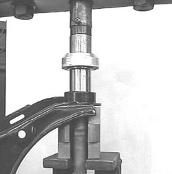
Figure 8. This is a picture of the proper press setup with tooling to maintain alignment and apply the assembly forces to the bushing shell and A-Arm without distortion. Measure the diameters before you press and choose your tolerances to avoid trying to press more than 0.010” interference. Remember to chamfer the bushing shell to allow an easier start for the bushing you press and choose your tolerances to avoid trying to press more than 0.010” interference. Remember to chamfer the bushing shell to allow an easier start for the bushing. |
|
|
After the bushing are installed, the internal bushing tubes are removed and the drill guide fittings are reinstalled and the grease path is drilled through the installed bushing shell and the body of the urethane material to the surface intercept of the inner pivot tube. This intercept area is the reason that the inner tube was prepared with a radial relief. This relief allows grease to flow around the complete circumference of the tube. After the drill chips have been removed the inner tubes are reinstalled and Zirc fittings can be installed and lubrication applied.
The remaining photos show some close-ups and details of the bushings and A-Arms and my recommendations for welding to provide permanent attachment of the spin weld tubes to the A-Arm structures. All welding operations are done to the bare, properly cleaned A-Arm structures.
| The Sunbeam Specialties Part numbers for appropriate related suspension parts are as follows: |
| Set of 8 Black urethane (4 upper, 4 lower) bushings |
FS-78 |
| Set of 8 Red (HP) urethane (4 upper, 4 lower) bushings |
FS-78H |
| Lower Ball Joints, each |
FS-53 |
| Upper Ball Joints, each |
FS-57 |
| Upper Beveled Thrust Washers (Set of 4) |
FS-67 |
| Lower Beveled Thrust Washers (Set of 4) |
FS-62 |
 **
**