Page 1
Cylinder Heads and Intake
Installing The Trick Flow Twisted Wedge Heads
Preparing to install cylinder heads involves a significant amount of advance preparation. The heads I purchased were one of the early sets intended as a direct bolt on replacement for the stock heads with the pedestal mount rockers. These heads were the ones that were plagued with problems resulting from people stepping up to high lift aftermarket cams and not necessarily correcting or checking all of the valve train geometry. The result for the owners of these heads was a lot of headaches and bad PR for TFS. TFS as a result set up a comprehensive warranty program to convert all of the pedestal mount heads to the screw in stud versions (I opted for the robust 7/16 inch studs ARP #1007101 and Comp Cams Pro Magnum stainless rockers #CCA-1332-16), replaced all of the valve guides with more suitable bronze guides, supplied TFS guide plates and then re-machined the valve job. I sent them out for this work before I even touched the heads and once I received them back I completely disassembled the heads and ported the Intake and exhaust interior ports to insure smooth transitions around the seat inserts and out of the combustion chamber. I also polished the combustion chamber area and slightly smoothed the areas immediately adjacent to the valve seat-machining radius to ensure smooth airflow in and out of the chamber. It is important to note that the TFS head ports are very nicely finished as cast and required only a minimal amount of blending work for a picky guy like me.
Intake Port Matching
Next I needed to port match the heads to the intake as the RPM Performer intake ports were about a quarter of an inch narrower than the TFS head ports and the head ports were inconsistently rectangular. I mounted the heads on to the engine block with the old head gaskets and then secured a pair of new Felpro "Print-o-Seal" large port gaskets (#1250) that very closely matched the TFS heads intake ports. With the heads mounted I sprayed the intake head surface with layout bluing ink. I then fitted the gaskets to the heads and marked the locations of the outer edge of the gaskets as well as the port locations scribing lines into the bluing ink. With the locations of the gaskets clearly marked on both heads I mounted the intake and marked the location of the intake both to the head as well as to each gasket edge by scribing a line along the edge of the manifold on the gaskets and the gasket edge on the cylinder head. You can see the gasket edge scribe in the picture Locating Scribes. After locating the port shape I used a straight edge to set a consistent register across the top and bottom of each port.
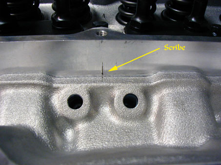
Locating Scribes
I used small dimples and a chisel mark to ensure accurate locating of the intake to the cylinder heads on reassembly. I removed the Intake and the gaskets and then coated the intake port faces with bluing ink and then mounted the gaskets to the intake face so that the marks along the gasket corresponded to the edge of the Intake manifold.
With the gasket clamped to the intake I scribed the port shapes on to the intake manifold. With the port shapes now scribed on both the head and the intake I dug out my die grinder and removed a lot of aluminum. The finished cylinder head ports can be seen in the picture Intake Porting. Note that the Cylinder head ports are not as clean or as perfectly rectangular shaped as the intake ports. The TFS castings had some casting inconsistencies and in some of the ports the port was slightly wider than the Felpro gasket opening along one edge while still being perfectly aligned with other ports. I aligned the gaskets as well as I could and ultimately decided to leave the mismatched port edges as correcting it would not have produced significant enough gains for the effort involved to increase the volume of all of the ports to match the irregular ones. In fact the extra intake track volume necessary to correct the shape may have had negative impacts on the intake charge velocity, potentially decreasing the overall torque potential of the total combination.
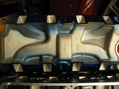
Intake Porting
The picture Intake Porting shows the completed porting of the RPM Performer manifold after matching the ports to the cylinder head ports and the Felpro gasket. I blended the port back as far as I could reach into the intake port, which was about 2 inches and widened the port to match the entry into the cylinder head. When looking to build torque, increasing the volume of the intake runners is generally a bad idea. However, the large entry of the intake to the small exit from the intake transitioning to the large entry of the TFS head down to the small quench around Intake valve would likely have had a detrimental effect on overall Intake air charge velocity. What I have achieved is a relatively smooth and consistent transition from the carburetor to the intake valve. I also machined a transfer slot in the intake plenum area as it appears on the new RPM Air Gap Performer version. This is a trick used back in the 1960’s to improve upper RPM performance of the Old GM dual plane LT1 intake manifolds with no consequence to low-end performance. The fact that the RPM Air-Gap manifold performs slightly better at higher RPM than the RPM Performer is likely due to this little machining difference (that is easily duplicated) and not the fact that it has an air gap underneath the plenum. Note picture Intake Plenum Slot.
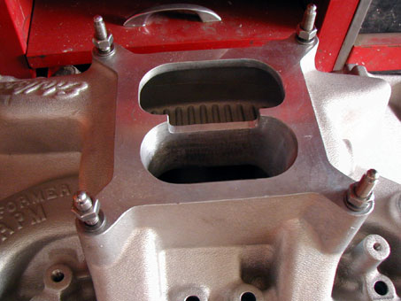
Intake Plenum Slot
Exhaust Ports
I used Felpro gaskets #1415 for the exhaust ports and again the ports had some minor inconsistencies between them so some of the port shapes are not exactly identical. I used a trapezoidal shape as I have read about the viewpoint of the “D” port shaped exhaust and felt they would be best for the TFS heads. Again, the size and location of the hole in the gasket and the location of the exhaust port relative to the other ports limited me but I did my best to keep them consistent. On some ports I was unable to widen the floor enough to achieve the optimal “D” shape as can be seen in the picture on the left most port. My rationale for the “D” port goes like this; Unlike the GT 40X heads the TFS heads have virtually no swirl to the intake charge and the Exhaust pulse is about the same. As the exhaust pulse is pushed out of the head it has to make a 90-degree turn into the exhaust pipe to exit the chamber. Gas under pressure tends to act like a liquid and the gas on the short side (bottom or floor) of the port has less distance to travel out of the port compared to the long (top or roof) side of the port so the gas on the bottom moves slower relative to the gas along the roof of the port. To minimize turbulence the “D” shaped trapezoidal port has a slightly narrower port on the top side of the port to compress the “fluidlike gas” and accelerate it slightly relative to the gas flowing at the bottom of the exhaust port. The result is that all the gas entering the port at one time hopefully exits at the same time resulting in a turbulent free pulse and improved scavenging of the combustion chamber. To help this effect I actually enlarged the header opening slightly so that it is just slightly larger than the exhaust port to help create a “reversionary deflector” out of the cylinder head face around the exhaust opening so that as gas pressure tries to push back into the exhaust port as each exhaust pulse exits the cylinder head in the center of the pipe the head face helps to deflect the pulse that is displaced by the exiting charge.
 **
**