Page 2
Once the longer push rod was installed it is obvious how it corrected the geometry. It is clearly better in the next picture 500 Long Push Rod. You can clearly see that the rocker roller is neatly centered over the valve stem tip and is almost perpendicular to the rocker stud.
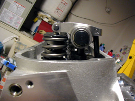
500 Long Push Rod
After correcting the obvious geometry issues a test I do is to rotate the engine and observe the pattern left by the rocker on the valve tip. I use a little Lubriplate and coat the tip of the valve stem and carefully assemble all of he parts being careful not to move anything. As you can see the pattern in the photo Rocker Pattern is right in the center of the valve stem and is about .150 inch wide.
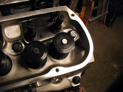
Rocker Pattern
Now that we know the geometry is correct and that we will obtain all of the lift at the valve that we should we can now carefully check for valve to piston clearance. Normally you would do this much earlier than this, as you want to avoid disassembly if possible in the event of interference. The simplest and most efficient method is to place modeling clay on the surface of a piston, tighten a head down, assemble the solid lifters and related valve gear like rockers and pushrods and slowly wind the motor over twice. Be sure to completely fill the valve pocket with a decent amount of clay. In my engine I was very confident that I had enough clearance but I did the test regardless as it is just too easy.
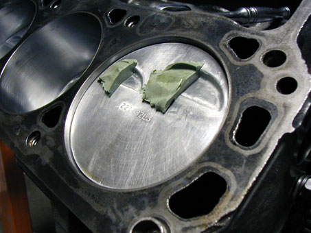
Valve to Piston
The results can be seen in picture Valve to Piston. After you remove the cylinder head carefully cut the modeling clay along the center and peel away half of the clay being careful not to disturb the other half. As you can see I have a boatload of clearance with the cam timing set as it is and this is without head gaskets. It is important to note that if you find it necessary to re-index (Advance or Retard) the cam you will need to recheck valve to piston clearance to remain confident that you have enough clearance.
Degreeing the Cam
Now that we know we are not going to bend any valves or pushrods by hitting the pistons or coil binding the springs and have ensured that the geometry is correct we can now begin to index the cam.
Generally, you want to remove the high-pressure springs and use some weak ones for this exercise as it makes it easier to rotate the assembly slowly and hit the degree marks accurately. Unfortunately I already had completely assembled my heads so I decided to take the “muscle man” approach and chose to not disassemble the heads.
You now need to gather the tools you will need:
- Magnetic base dial indicator
- Timing Wheel
- Some wire to fabricate a timing pointer
- The exact cam specs as found on the Cam card
- Some method of turning the crank slowly and precisely
- Some method of a Piston Stop
Begin by attaching the timing wheel to the front of the crank either by bolting using the center balancer retaining bolt or by temporarily mounting the balancer and bolting the timing wheel to that. I chose to just bolt the timing wheel directly to the crank. Once it is secure mount the pointing wire so that it points to the timing wheel in such a way as to be an indicator of the degree reading on the wheel. The specific orientation of TDC or the pointer is not important just yet (although I always try to orient it close to where factory TDC would be); you just have to be able to read the pointer and the degrees indicated.
Finding TDC
Now that this is firmly attached you need to fashion a solid piston stop. I did this with a piece of bar stock with a bolt through it that extended down into the piston bore on the #1 piston. It was bolted to the top of the cylinder bore through head bolts holes so that it was supported on both ends and the bolt stuck down half an inch into the bore in the center. With this firmly attached carefully rotate the motor in one direction until it just makes contact with the stop. Apply pressure to ensure it is firmly stopped and take a degree reading on the wheel. Now rotate the engine the other direction until it stops again and take a reading. Repeat this step to ensure that nothing has moved and if the readings are repeated you simply note the degree measure on the wheel that is exactly half way between the two opposing points. Unbolt the piston stop and rotate the engine so that the pointer points to exactly the halfway point between the two measures. Your engine is now at EXACTLY TDC for the number one piston. This is the best time to verify your timing marker to the indicated TDC on your balancer if you wished to. If the timing marker and the wheel are not oriented to make it easy to view, now would be the time to readjust everything so that the indicator and the wheel are set up so that they are convenient to read. Be careful to not move the crank at all otherwise you will need to start all over with the “Finding TDC” exercise.
Indexing the Cam
Now that we have the short assembly set up to do the measuring we need to install the cylinder head, solid roller lifters, pushrods and rockers. Rotate the engine to the small base circle of the Cam and adjust the rockers for no lash using your hands to ensure that you do not over tighten the valve and depress it any distance.
Now we need to refer to the cam card for the specs to determine if the cam is indexed correctly with the crank and the timing chain and gear in place. Some cam specs are measured at the tappet and some are at the valve be sure which your cam card refers to.
For my purposes I used lift at the tappet and the specs are as follows at .050 lift the card indicates that the intake opens at 5.0 degrees BTDC and close at 39.0 degrees ABDC. The exhaust at .050 inches of lift opened at 53.0 degrees BBDC and closed at –1.0 degrees BTDC.
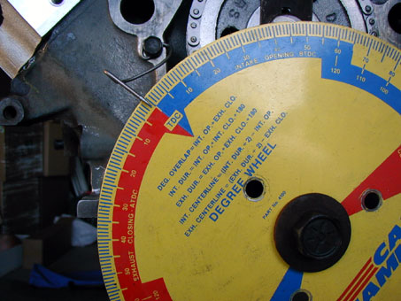
Exhaust Closing
With these specs in mind we simply rotate the engine until we achieve .050 tappet lift and read the indication on the timing wheel. If the number is correct we can carry on, if not we need to determine whether it is advanced or retarded compared to what was intended by the cam company when they ground your particular cam. The idea is that we want the Cam oriented exactly as the cam company intended so that it performs as intended. For my engine the Exhaust closed at exactly –1 at .050 inches as in the picture Exhaust Closing. The Intake closed at 40 degrees when tappet lift was at .050 on the closing side of the lobe and this could be due to some error I made or some variance in the wheel mounting as everything else seemed perfect. Since it was so close I did not worry about it and left the cam timed straight up on the adjustable timing chain crank gear. I will try this set up but if the engine seems a little lazy I will try to advance the cam 4 degrees to wake up the bottom end performance as I am building a low RPM combination. Now with the Cam timing verified we can move on to installing the cylinder heads.
 **
**