Page 1
Measure Valve Lift
Two prior articles, modifying the firewall to provide Clearance for Valve Covers , and building up the stroker block A 350 Lunati for a Tiger!, have been published. To complete the Lunati 350 long block we need to install the cylinder heads and camshaft.
There are a lot of interrelated tasks here so I will try to relate them in as organized a fashion as I can. I recommend that this only be a guide and you should rely on your own expert’s advice if you try this on your own.
On an advisory note: You will find the detailed information within this article describing why the valve cover height required clearance on the firewall described in the linked article. A summary would be, for power levels I desired, the choices of camshaft, rocker arms, valve stem length and spring height, etc. increases the overall height of the valve train from stock and requires that a taller the valve cover be used raised to allow clearance for the moving rocker assemblies.
If your personal choice is to retain the firewall in its original condition. This will limit the serviceability of some of the more extreme performance camshaft and valve train options available. They will still fit within the stock firewall cutout but will require dropping the engine down to permit removal of the taller valve covers from the engine over the raised rocker arm assemblies should you need to service the valve springs or rockers. Then the alternate choices in these items can be made, at the cost of maximizing power output. Everybody has to decide what is most important to themselves in order to make the best decision for their particular application and serviceability requirements correct compromises.
Selecting a Camshaft
The cam I chose is a Trick Flow Specialties Stage 2 cam with the following specs:
- Trick Flow Specialties (TFS) Stage 2 Hydraulic Roller Cam
- Duration at .050 inches Tappet Lift
Intake - 224 degrees
Exhaust – 232 degrees
- Valve lift with a 1.6 Rocker
Intake .542 inches
Exhaust .563 inches
- Advertised duration at .004 inches of Tappet Lift
Intake – 286 degrees
Exhaust – 294 degrees
- Lobe Centerline separation 112 Degrees
Selecting a cam is one of the most crucial aspects of creating an engine combination that will work with maximum efficiency. In my case I was looking to maximize torque at the lowest RPM possible. I would have preferred a tighter lobe separation than 112 degrees but currently there are not a lot of options for the hydraulic roller setups as most are ground for fuel injection systems with the wider 110-112 lobe separations. In the past I have had excellent success with race roller cams intended for short circle track events in my street performance cars with lobe centerline separations of 104-106 degrees. In this case I will have to wait and see how it performs after we get it running but in the meantime I expect that the cam will produce adequate vacuum for the Tiger power brakes. Another consideration is that the substantial extra 48 cubic inches of the Lunati 350 will act to “kill” a little of the cams street raunchiness resulting in a more docile acting cam than would be experienced in a 302 displacement engine similarly equipped.
Good Valve Springs are Essential
Having similar duration to a Comp Cam 292H Hi-Energy Flat Tappet Hydraulic Cam, the TFS roller cam is able to achieve higher average valve lift numbers as the valve is opened more rapidly and held open longer at higher lift values due to the roller tappets ability to make use of more radical ramp profiles on the cam lobe. The irony is that even though the cam profile is more radical ultimately the arrangement is far more durable than a stock flat tappet hydraulic arrangement. Roller Kits are made that can retrofit to the stock 260 and 289 engines for around $800 and would provide a significant improvement over the stock flat tappet or the “performance” flat tappet cams that were historically available. Given this more radical profile it is imperative that sufficient valve spring pressure is maintained to ensure that the roller remains in contact with the cam lobe at all times. If the roller is permitted to “bounce” on the lobe of the cam, a condition that can occur at valve float when you exceed the operating range of the valve spring, cam failure will result. This bouncing can also occur at idle if you do not run sufficient spring pressure to ensure that the roller follows the cam lobe during normal operation. The cam spec card did not include the spring pressures required so I had to follow up with TFS by telephone and they indicated that 130 lbs seat and 350+ open pressure would be sufficient.
I had purchased the upgrade kit from TFS (spring kit #TFS-31400414) which presumably had the correct Crower springs but after checking them they actually coil bound when set up for the installed pressure and required lots of shims to get a paltry 115 lbs at 1.800 inches. I purchased a set of Lunati double springs (#73100 ) that were just right for the Twisted Wedge Heads actually fitting into the hardened spring seats better than the supplied previous springs, Lunati saved me again! I also purchased a Tavia Valve spring compressor to check each spring. The specs called for an installed seat pressure of 125-130 lbs. for new springs as they will lose about 10 pounds once they are run resulting in an actual 115-120 lbs. seat pressure once they are run in. The actual Valve spring retainer heights with the keepers (Comp Cams Valve lock (part #CCA-648-16) in place measured at 1.880 Exhaust and 1.860 Intake on the cylinder head. I did not have a height micrometer so I relied on Bob McKray at Bob McKray Performance in Mission Viejo, CA for his expertise and of course …. the “Height Micrometer”.
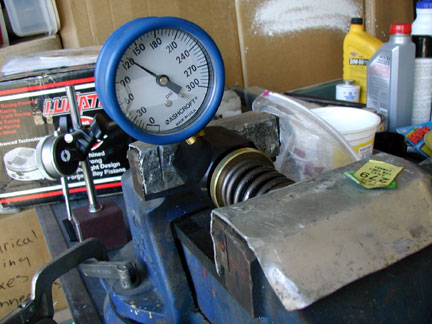
Spring Pressure
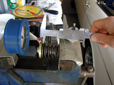
The other Spring Height
In the picture Spring Pressure you can see the pressure at the installed height for this particular spring at about 128 lbs. using a Tavia spring pressure tester. This tester ranks up there with one of my best purchases as it works very accurately and is very portable. I did verify the tester with a local performance head shop with no variance in the readings. The second spring picture, Spring Height , shows how I measured the height with a caliper to the base of the retainer. You are not able to see the retainer but it is definitely there. I achieved adequate pressure at 1.850 spring height requiring .010 and .030 hardened shims to ensure correct spacing for the installed heights available on the Twisted Wedge Heads.
Installing the Cam
Once all of the parts are cleaned lubricate the cam with bearing lube only on the cam bearing journals. Use plain engine oil on all of the cam lobes as engine assembly and Cam lube are NOT recommended on the lobes of a roller cam and then stick it in by slowly rotating the cam as you insert it. Once it is in, install the retainer plate and torque the bolts to the Ford specs.
The timing chain should be soaking in a container of oil to ensure it is completely saturated with oil and if it wasn’t do it now and wait at least an hour moving the chain around while submerged. After the chain “christening” install the True roller timing Chain. If you have an advance capable timing chain set I recommend installing it with no advance or “straight up” as they gear-heads say until we verify the cam indexing by “degreeing” it (More gear-head slang).
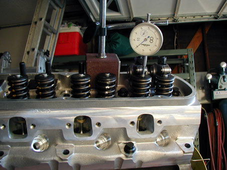
Valve Train Geometry
We are now ready to begin measuring the cam timing but to do so I like to measure it at the lifter. To ensure the lifter if firmly seated against the cam I like to have the valve spring pressure against it. The orientation of the rocker to the valve stem is important to ensure everything is configured correctly ensuring that the spring pressure is transmitted properly to the lifter. I have found that it makes more sense to correct valvetrain geometry at this point in the process of engine assembly. The first thing I did was to build some solid roller lifters from the factory Ford units I had. This can be accomplished by popping the retainer clip out of the top of the lifter and reversing the little plunger, and then grinding off just enough from the plunger to enable the retainer clip to go back in. This arrangement provides you with a nonfunctional solid (was hydraulic) lifter so be sure to mark it so that it does not find it’s way into an engine inadvertently. With the solid lifter you can now proceed with the valve train geometry verifications.
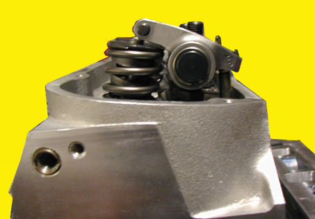
Stock Pushrod Length
The stock Ford pushrods are not long enough for use with the Twisted Wedge heads as can be seen by the rocker orientation in the picture Stock Pushrod Length. It is obvious that the rocker is sitting right on the edge of the valve stem tip and serious side loading and valve stem damage will occur if you attempt to run this setup. I chose to run a .500 long .080 wall pushrod from TFS. This is shown next to the stock pushrod in the photo Pushrod Comparison. Once the correct length of pushrod is determined it is important to align the guide plates to have the rockers center themselves over the tip of the valve stem. In my case it was a matter of splitting the difference and getting it as close as possible as they were not aligned as well as I would have liked but should work sufficiently.
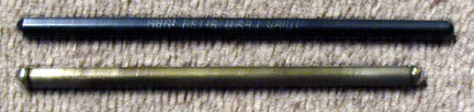
Pushrods Comparison
 **
**