A 350 Lunati for a Tiger!
An Article by Tim Ronak
February, 2002
Page 4
Installing the Crank
I cleaned each bearing shell with solvent and a clean rag and then blew lightly with compressed air. I laid the bearings out in sequence on a clean cloth and I then gave the block one last wipe where the bearings were to be installed. As you are doing this be sure you have cleaned EVERYTHING and blown ALL of the journals out thoroughly because there is no turning back now. Check all of the bearing shells closely for any damage and if there are any protrusions at the parting line clean these off carefully with a razor blade or sharp pocketknife. Install all of the shells into the block and the corresponding main caps. Clean the area around the rear main seal area and apply an adhesive to the edge of the rear main seal itself AFTER cleaning the outer edge of the seal with brake clean and wiping that edge with a clean rag. Now use some engine assembly lube on each bearing surface and the crank journal where the rear main seal is going to ride as well as inside the rear seal lip. Now place the one-piece rear main seal onto the rear of the crank and GENTLY set the crank into the upper bearing shells. Carefully place the caps onto the block and lightly tighten the bolts leaving the thrust bearing bolts slightly loose but snug (This is the number 3 Journal). To set the thrust bearing there are two methods. 1 – Use a rubber mallet (or Block of wood) to drift the crank fore and aft 2 or three times to ensure that the thrust bearing (Number 3) is perfectly aligned. 2 – Use a bar or large screwdriver to gently pry the crank fore and aft several times to ensure that the thrust faces are perfectly aligned over each other. Now torque your bolts to the recommended specs. I used ARP fasteners, which call for lubricant and different torque specs than FORD. I choose to torque my bolts up in three steps increasing the amount of torque three times. I start at one setting and then torque all of the bolts and then move to the next setting…etc. It does take a little longer but if you are in a hurry then you better get someone else to do it because you will just screw it up. The key is cautious confidence.
Now we need to check for crank endplay. This is done by placing a dial indicator on the front of the block and setting it to read of the crank snout as in picture Crank End Play. Now pry the crank fore and aft and read the amount of travel the crank has. Mine had .005 - .006 if I recall correctly. You can use the specs from Ford (.004 - .008) for this measurement.
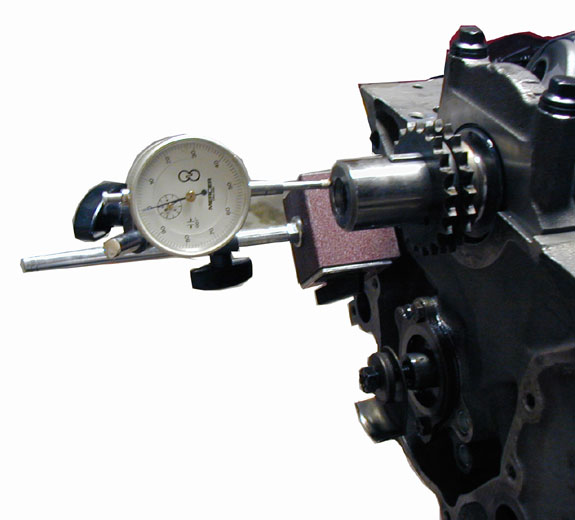
Crank End Play
Installing the Pistons on the Rods.
If you have full floating pistons you may very likely install the pistons yourself. If they are pressed pins then you will probably have a machine shop do it for you. If you do choose to install these yourself be sure to orient the wide chamfer on the big end of the rod correctly to ride against the crank with respect to the valve reliefs. The valve reliefs should curve up with the flat side of the relief facing towards the outside of the block as in the picture Twisted Wedge Pistons. Note that the twisted wedge pistons have been de-burred around the valve reliefs to prevent any sharp edges from pre-igniting and that the valve reliefs are significantly out of line as compared to a stock Ford or replacement piston.
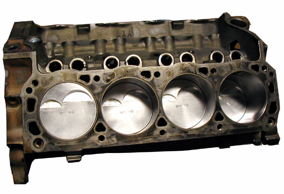
Twisted Wedge Pistons
Once all of the pistons and rods are assembled install the rings. Install the ring land support provided by Lunati and ensure the split is located around the piston as per the instructions with the gap/split 90 degrees opposed to the piston pin. Ensure that the little dimple that locates the ring land support is correctly located in the area of the wrist pin and facing down against the ring land so that it will prevent it from rotating. Then starting with the oil rings wind the center corrugated component of the Oil ring on to the piston, then wind the skinny retaining rings bottom first then top being sure to orient the end gaps as indicated in the ring instructions. Then use a ring expander on the second rings and finally the compression ring to insure that you do not twist the ring and crack the moly filling. I assume you have already file fit them to each bore or are using “ready to install” versions. Simply ensure that you have at least .004 inches of gap for each 1 inch of bore diameter. There are usually instructions with the ring package as to how to orient your rings but in general you do not want to align any of the gaps with each other. You also do not want any of the rings with its gap in line with the wrist pin and you want to watch out for which side of each ring is to face upwards.
Once these assemblies are ready we then need to install them into the engine block. Prepare each rod for assembly by organizing them on a bench with their matching caps and install the bearings in the same manner as used for the crank including lubing liberally with engine assembly lube. Use a tapered cone ring compressor, as they are the best in my books. Pour a little engine oil on the rings and wipe the bore with some oil as well. It is impossible to use too much. Poke the rod base through the machined ring compressor cone and get all of the rings started into the cone. Place some 6-inch plastic or rubber fuel hose over the ends of rod bolts if you have rod bolts to protect and guide the rod bolts past the crank journal surface. My rods used Cap Screws so this was a little more difficult as there was nothing to hang on to on the big end of the rod. Slide the big end of the rod into the cylinder bore and firmly secure and align the machined cone over the bore. Once you are sure the plastic tubes are correctly passing the crank use a wooden or plastic end of a standard hammer or mallet and tap the piston into the bore in two or three quick but firm taps until the top of the piston is just flush with the block, remove the tapered compressor and continue tapping until the bearing just seats against the crank and you start to see bearing lube squish out. Now place the matching rod cap oriented as well with the large chamfer against the crank radius and lightly take up some slack BUT DO NOT TIGHTEN until you have the other connecting rod beside it or you may damage your rod bearings. Repeat this for each connecting rod. Once they are all installed snug them up and torque to specs in pairs. If you have more expensive fasteners you may want to tighten referring to bolt stretch.
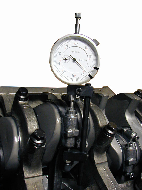
Bolt Stretch
This is definitely the preferred way as it ensures exactly the intended preload for each bolt. You do this by using a rod bolt-stretch gauge as in picture Bolt Stretch. My Lunati Cap Screws called for .0045 - .0050 of stretch. Check your Rod side clearances mine were .014 and compare them to Ford (.010 - .020) and you are all done for now. Have a beer and sit back and Bench Race for a while.
You now have a complete lower rotating assembly! Next articles are installing and degreeing the Cam and later the Cylinder Heads.
Read the "Next Chapter"
 **
**