"Lucas, Prince of the
Intermittent Windsheild Wiper"
or,
How to Make a Real One!
An Article by Ed Esslinger
June, 2002
Page 3
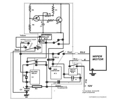
- SUNBEAM WIPER CONTROL - HOW IT WORKS
(SEE DRAWING)
Note:This circuit is designed for negative ground cars. A small change to the unit and connection hook up is used for positive ground cars. If used on Series 1 or 2, the wiper switch will have to be changed to a Series 3-5 or Tiger type.
Caution: Handling assembling, and soldering solid state components requires appropriiate soldering techniques, equipment, and grounding to prevent component damage.
HOLDING RELAY K1
The purpose of this relay is to insure that when the IGN is switched off, power is removed from the MAIN CONTACTOR K2, therefore removing the ground to the motor and through its parking contact, allows it to park.
With the IGN switch on, C1 is charged to 12V through R1 and applied to one side of the coil. When the wiper switch is turned to the on position, the other side of the coil is grounded. C1 discharges and closes K1 long enough, for the holding contacts to supply 12V to the coil, recharging C1 and keeping the relay closed until the IGN switch is turned off.
If the Wiper switch is left in the on position, C1 cannot charge due to the resistance of R1 and coil of K1 that is grounded. When the wiper switch is placed to the off position for a few seconds C1 can charge and everything will work normally.
MAIN CONTACTOR RELAY K2 Opens or closes the ground connection to the wiper motor.
DELAY RELAY K3 Supplies 12V to the motor for a few seconds after the IGN switch is turned off due to the charge on C2. It receives its contact voltage from an un-switched 12V source. This insures that the motor will have voltage long enough to park.
INTERMITTENT CONTROL RELAY K4 Switches the Intermittent circuit out when normal speed is selected. Removing its ground at the wiper switch does this..
INTERMITTENT CONTROL CIRCUIT. Q1 Is held off by voltage divider R3 & R4. C1 charges through R1 & R2 and overcomes the bias on Q1 causing it to turn on. R5 supplies the bias to turn on Q2 closing the MAIN CONTACTOR relay momentarily and discharging C1. about every 5 seconds.
Note: Diodes 1N4007 CR 3 and CR 4 are added since first release
in order to surpress switching transient across relay contacts.
|
Anyone who would like to contribute to this effort should contact us at Editor E-Mail. Thank you. |
 **
**