|
ARMREST
To remove
To remove the combined centre armrest and locker, tip both the driver’s and passenger’s seats forward. Remove the three self-tapping screws from each side of the arm-rest, and lift off.
Refit by reversing these operations.
HEADLINING
To remove
Remove the hardtop.
Remove the backlight and quarter lights.
Remove the weatherstrip from the forward edge, and the furflex piping from the sides of the hardtop. Release the edges of the headlining from the flanges of the hardtop, and release the lining.
All edges are secured to the flanges in production with an adhesive, solution.
Release the listing rods and remove the lining.
To refit
The headlining listing rails can only be fitted in one position. Secondly, attach the lining at the rear corners, taking the tension before sticking down to remove wrinkles.
Attach the front edges working from the centre out-wards, following with the side edges last.
Note
Before sticking the edges down, all wrinkles and creases must be eliminated and no sagging should occur when finally fitted.
Re-attach the edges of the lining to the flanges of the hardtop, following with the weatherstrip at the forward edge, and the furflex piping at the sides.
Replace the backlight and quarter-lights. Refit the hardtop.
DOORS
Lubrication
It is essential that the hinge pins and door locks are lubricated at regular intervals.
The wards of the lock should be lubricated by applying oil to the key, which is then inserted into the lock in the normal manner.
The push-button of the exterior handle is lubricated from the outside.
To adjust hang of the doors
Note: If hinges are adjusted, then the door lock striker plates must also be adjusted.
|
Adjustment of the doors is carried out by loosening off the bolts securing the hinges to the body, and moving the doors in the required direction, after which the securing bolts must be re-tightened.
In order to raise or lower the door diagonally, packing pieces of the required thickness may be fitted between the hinges and their respective attachment points.
If damage to the locks, the door components, and trim is to be avoided, the following dismantling InstructIons should be adhered to.
DOOR LOCKS
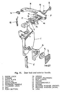
To remove (Fig. 11)
Remove the interior trim.
Remove the securing screws which hold the remote control to the door and swing the unit and connecting link vertically downwards. In this position, the unit can be detached from its dowel on the operating lever of the Lock.
Remove the securing screws in the shut face of the door and the screws securing the dovetail on the inner door panel.
The lock unit is now free to be removed through the lock aperture.
 |
 **
**
