Upgrading the Tachometer for use with Electronic Ignitions
An Article by Tom Hall
One of the frustrating issues related to upgrading your Tiger ignition system are the problems those improvements cause in your tachometer operation. Although a change to a Pertronics point-less trigger system normally causes few problems, a serious upgrade to a state of the art ignition system typically results in partial or complete loss of tach operation. This tip is one way to get your tach back into a more responsive mode. The modifications shown were 
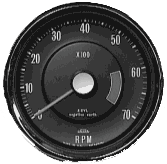
Figure 1: The 7K Alpine tachometer.
made on a 7,000 RPM Alpine instrument, but should work as well on a normal Tiger tach.
The trick involves substituting a capacitance coupling to drive the instru-ment in place of the current pulse counting primary wire loop. The starting point is a capacitor in the .0047 MFD to .01 MFD range, rated for at least 12 volts. These are available from Radio Shack or similiar suppliers for about $.59 a pair (RS P/N 272-134 or 272-130). One side of the capacitor is connected to the secondary of the pickup coil, which is identified by the black wire. The best place to accomplish this is to solder it to the pass-thru connector on the circuit board.
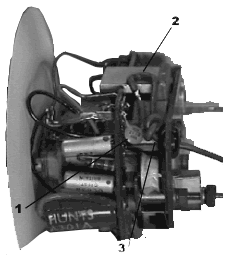
 Figure 2: Internal wiring modifications.
The other side of the capacitor will be connected to your electronic ignition tach output, but letÍs make this a reasonably sanitary modification. Upon carefully ex-amining the circuit board, you can find a location to drill a hole for a rubber grommet to insulate the wire. By passing the wire through the grommet and knotting it, you can make a very nice strain relief (see No. 3 in Figure 1). I looped the wire over the metal shown at No. 2. and applied a couple of drops of super glue to keep it from wandering. A small sleeve of insulation over the wire leading from the capacitor and a solder connection completes this new input.
My preferred grommet location is more clearly shown as No. 1 of Figure 3. Also more visible in this shot is the calibration adjustment pot used to correct tachometer response. It is shown as No. 2 in Figure 3. The new lead wire to the electronic input is No. 3 in this figure.
Next , you need to drill a hole in the metal case to clear the new grommet.
 1 | 2 | 1 | 2 |  |
 **
**


 Figure 2: Internal wiring modifications.