|
Differential bearing adjustment
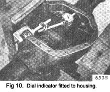
When fitting the differential assembly to the casing, always fit the dial indicator to the casing to register the amount of spread (Fig. 10). Do not exceed a maximum of .008 in. (.20 mm).

The thickness of the shims required in the installation of the differential bearings is determined as follows
Fit the differential bearings without shims, on the dif-ferential case, making sure that the bearing cups and cones and the housing are perfectly clean.
Place the differential assembly, with the bearing cups in their housing, within the gear carrier, the pinion not being assembled.
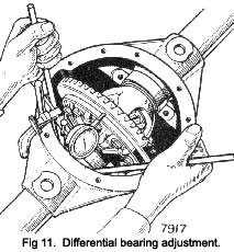
Install the dial Indicator set on the gear carrier with the button against the back face of the drive gear.
Insert the two levers between the housing and the bearing cups moving the differential assembly to one side of the carrier (Fig. 11).
Set the indicator to zero.
Move the assembly to the other side and record the reading which gives the total clearance between the bearings as now assembled and the abutment faces of the gear carrier housing.
Add .005 in. (.i3 mm.) to the reading to give preload. This thickness of shims must be used in the installation of the differential bearings, the shims being divided to give the gear position with correct backlash as detailed under “ Drive Gear Adjustment” on Page 10.
|
Pinion adjustment
Re-install the pinion outer bearing cup with tool No. SL.SSO-4. Re-install the pinion bearing inner cup with the original size adjusting shims fitted, using Tool No.
SL.550-5.
Press the inner bearing cone on the pinion, using an arbor press, and a length of tube, contacting the inner race only, and not the cage, or use Tools RG.4221B and SL 14-1. The hypoid drive pinion must be correctly adjusted, before attempting further assembly, the greatest care being taken to ensure accuracy.
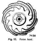
The correct pinion setting is marked on the ground end of the pinion (See Fig. 12).

The matched assembly serial number at the top is also marked on the drive gear, and care must be taken to keep similarly marked gears and pinions to their matched sets, as each pair are lapped together before dispatch from the factory.
The letter on the left is a production code letter, and has no significance in the servicing of the axle.
The letter and figure on the right will also be found stamped on the casing. If at any time, a replacement crown wheel and pinion are fitted, the replacement set
|
 **
**


