LAT-1 FACTORY INSTALLATION INSTRUCTIONS
Thanks to Ed Esslinger for the copy of the instructions!
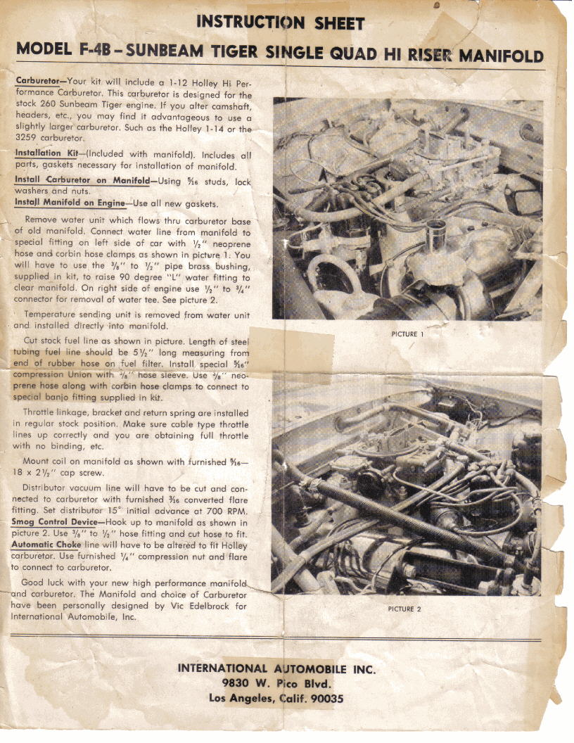
This copy of the Rootes LAT-1 F-4B installation shows some of the differences between the commercial
Edlebrock F-4B and the one sold as the LAT option.
Although it cannot be discerned in the photo, the temperature sender threaded hole near the main water hose is a straight, fine pitch thrread, not the pipe thread on the commercial model. (obstructed by Coil high tension lead). "Picture 1" shows a right angled fitting coming out of the left front intake manifold runner This is usually an undrilled boss in the commercial model.
It is used to supply a vacuum source to the power brake servo thru a long hose."Picture 2" shows the fitting to the right rear manifold, usually used for the brake servo, connected to the PCV valve.
The manifold volume at this point is much larger, and the sump gas flow does not adversly influence the fuel-air mixture in the manifold. Such a flow volume would influence a single runner, however, so Edelbrock connected that new fitting to the brake servo, using a clumsy long hose, as the servo only requires a large flow on engine start. Braking use uses little air removal (vacuum replenisihment!) in the servo, normally,
The heater hose diameter adapter, usually handled within the removed 2 BBL carb spacer plumbing, is hidden inside the joint of the hot water from the engine front, and the heater core hose near the firewall.

 **
**

